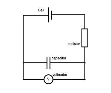
&Xw9 4p4vunct28,9C9q2By11/g57kWX.7O0/@:VpY,F4`E_/81 (Q You will find the relationship between the voltage and current in a diode, and study temperature effects, rectification, nonlinear phenomena, and frequency doubling. Web3. The term used for the resistance these elements offer to current flow in AC circuits is reactance. eQZav___smU? The power supply was feeding 4 V during all three experiments. This is the sim for you! Therefore, the smaller the value of , the faster the circuit response is. hR9`A**dbe{99nB\i$PXB:|! First measure the capacitance of the large capacitor provided using a capacitance meter (the nominal value is 47 F) . )#jm2U;C&^vq-3x+e6|4D/FdMXTs\^I wQ/L,xlbv1dP3QH2.7&l. Her reaction to the message is an example of a. If you plot the capacitor voltage versus time, it will look as shown in Figure 4.

Don't have an AAC account? 4 0 obj Mathematically, we say that the phase angle of a capacitors opposition to current is -90, meaning that a capacitors opposition to current is a negative imaginary quantity. The characteristic equation usually takes the form of a quadratic equation, and it has two roots s1 and s2. Step 7:You can also simulate the circuit of Figure 6in SPICE and plot the exponential charging of the capacitor voltage. WebFigure 2: (a) Capacitor circuit symbol (b) Polarized capacitor In this lab we will become familiar with capacitors - in series and parallel - in circuits using the breadboard.
This lab's goals were to teach students about the characteristics of AC circuits and to look, into how voltage and current behaved in circuits containing resistors, capacitors, and diodes. You should already know by now how multiple resistors need to be connected to form a greater total resistance. Zoom in on the output curve on the oscilloscope such that a large portion (at least half a cycle) of the rise/drop of a cycle is displayed on the screen. well as verify that Va + Vb is equal to V0. Turn off the input (Channel 1) by pressing the channel number button.
This means that a capacitor does not dissipate power as it reacts against changes in voltage; it merely absorbs and releases power, alternately. What do you observe? See Fig. 1L` We used the PASCO interfaces signal generator to create an alternating Figure 4 5 and Figure 4 6 show various 2nd order circuits. The capacitor will start to charge and you will see the capacitor potential difference increase. Step 4:Try to change the RC time constant by adding an additional capacitor to the charging circuit. KEPERLUAN Tugasan 1 (30 markah) Rumuskan konsep metafizik (kematian), The following transactions of Aroma Trading occurred in April 2022: Aroma Trading paid an insurance premium for six future months' worth of coverage. First-order transient circuits are described by a first order differential equation.
 WebExperiment Build the circuit on breadboard, and use the same input settings as in SIMULATION. 105 0 obj
<>
endobj
Complete the measurements described below. The serial number for the capacitor was A-1678 and for the resistor was 48288. HS]k0}?G }Zyh What this means is that reactance in ohms for any capacitor is inversely proportional to the frequency of the alternating current. %
Next, it is educational to plot the voltage of a charging capacitor over timeto see how the inverse exponential curve develops. <>
u.wB&~W`'J{tZYS*77^l]*L;>O9LBzCa ma8X^ }b$]&ipd"!E`dO+%EP 0hAY{Q+(?l=gQr~5YV_~HwM#CbNN83<2,$ z&(+zg2`qzX`9WIDWzxG`%%7tptq(1}4/Mbg;yu8=,-:{G ttI{^@'O.kbgHzd!:o%q@oM U&QV.{VzTVj4szGi tYF6` 49B
To understand the concept of the time constant.
WebExperiment Build the circuit on breadboard, and use the same input settings as in SIMULATION. 105 0 obj
<>
endobj
Complete the measurements described below. The serial number for the capacitor was A-1678 and for the resistor was 48288. HS]k0}?G }Zyh What this means is that reactance in ohms for any capacitor is inversely proportional to the frequency of the alternating current. %
Next, it is educational to plot the voltage of a charging capacitor over timeto see how the inverse exponential curve develops. <>
u.wB&~W`'J{tZYS*77^l]*L;>O9LBzCa ma8X^ }b$]&ipd"!E`dO+%EP 0hAY{Q+(?l=gQr~5YV_~HwM#CbNN83<2,$ z&(+zg2`qzX`9WIDWzxG`%%7tptq(1}4/Mbg;yu8=,-:{G ttI{^@'O.kbgHzd!:o%q@oM U&QV.{VzTVj4szGi tYF6` 49B
To understand the concept of the time constant. 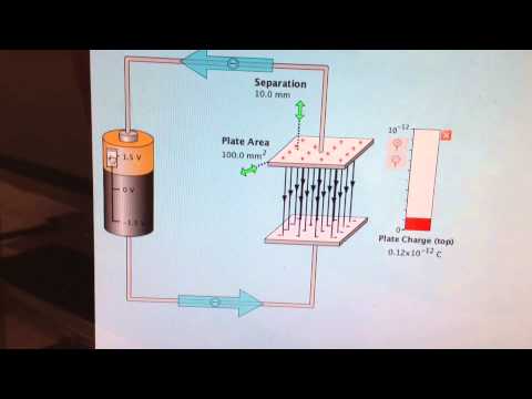 Since capacitors conduct current in proportion to the rate of voltage change, they will pass more current for faster-changing voltages (as they charge and discharge to the same voltage peaks in less time), and less current for slower-changing voltages. Please give a log explanation (15 marks) Give 4 suggestion ways to strengthen the movement of a trade union with clear justification.
 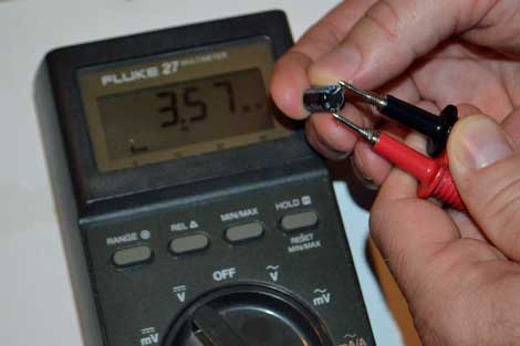 Equation 6.1, which gives the generic formula for the phase shift between two, periodic functions, is another one that applies to this lab. Aroma Trading's building is presented at a cost, Case 19: Worldwide Paper Company Case Study Essay Synopsis and Objectives The case is based on an actual investment decision made by a major paper-products company in the 1990s. 882 0 obj
<>stream
For each case, indicate if the output response is overdamped, critically damped or underdamped. stream
1 0 obj
%PDF-1.5
(a) (b) Figure 2 (a) RC circuit (b) Circuit diagram for t > 0 The general term for the sum of all the resistance and reactance @a0,;f= G. The formula is =t/T x 360, where t is, the time interval between the voltage and the current, Ti is the function's period, and is the phase, shift. Ya Shen 2. Web Further familiarize yourself with AC circuits and machines, and their analysis. z+t^D "XRI380{-T0`FRB.dhRERi0H--Wz_~[cxv34[O~B@7)ldO5{f`N<8 YaC]YXUpeDT>^5.EQnnVE]"WL*{x8XbaG?TuqPj67]*/J
Equation 6.1, which gives the generic formula for the phase shift between two, periodic functions, is another one that applies to this lab. Aroma Trading's building is presented at a cost, Case 19: Worldwide Paper Company Case Study Essay Synopsis and Objectives The case is based on an actual investment decision made by a major paper-products company in the 1990s. 882 0 obj
<>stream
For each case, indicate if the output response is overdamped, critically damped or underdamped. stream
1 0 obj
%PDF-1.5
(a) (b) Figure 2 (a) RC circuit (b) Circuit diagram for t > 0 The general term for the sum of all the resistance and reactance @a0,;f= G. The formula is =t/T x 360, where t is, the time interval between the voltage and the current, Ti is the function's period, and is the phase, shift. Ya Shen 2. Web Further familiarize yourself with AC circuits and machines, and their analysis. z+t^D "XRI380{-T0`FRB.dhRERi0H--Wz_~[cxv34[O~B@7)ldO5{f`N<8 YaC]YXUpeDT>^5.EQnnVE]"WL*{x8XbaG?TuqPj67]*/J  Consider the rise and drop over one half cycle only for each circuit. Always make sure that the capacitors polarity is correct! However, underlying all of these systems at a fundamental level is the operation of DC circuits. Ch~4%3FDK6w:9dTVFy"cTR*,D2B/1.YrW'e" aALx Oq! This lab uses liquid nitrogen (LN), which is very cold: approximately . We will also use a parallel plate apparatus to investigate its capacitance with di erent plate spacings, and types of dielectrics. Why? Since most single-frequency AC circuits have a sinusoidal voltage and current , exercises in Experiment 5 use sinusoidal AC voltages. The simulator provides a, graph that shows the signal's amplitude, frequency, and phase. As|,n89Nx
r^H3HQO ( p[c-!qlURhxEa 6KVN1@FvQ`R)c 3@xJ~J;
|]+Q/)3 lb:@i&o Resistors 3. Build this circuit and monitor the voltage change before and after closing the switch.
Consider the rise and drop over one half cycle only for each circuit. Always make sure that the capacitors polarity is correct! However, underlying all of these systems at a fundamental level is the operation of DC circuits. Ch~4%3FDK6w:9dTVFy"cTR*,D2B/1.YrW'e" aALx Oq! This lab uses liquid nitrogen (LN), which is very cold: approximately . We will also use a parallel plate apparatus to investigate its capacitance with di erent plate spacings, and types of dielectrics. Why? Since most single-frequency AC circuits have a sinusoidal voltage and current , exercises in Experiment 5 use sinusoidal AC voltages. The simulator provides a, graph that shows the signal's amplitude, frequency, and phase. As|,n89Nx
r^H3HQO ( p[c-!qlURhxEa 6KVN1@FvQ`R)c 3@xJ~J;
|]+Q/)3 lb:@i&o Resistors 3. Build this circuit and monitor the voltage change before and after closing the switch. Take measurements with a lifelike ammeter and voltmeter and graph the current and voltage as a function of time. Course Hero is not sponsored or endorsed by any college or university.
 Pr in ciples In an AC circuit the direction of the current changes s in usoidally with some angular frequency, = 2 f . The coupling capacitance C 1 lets only the alternative current (AC) signal pass as an input of the CEA configuration while blocking the direct current (DC) to go from the supply to the source. The signal length, l on the screen and the value of current on ammeter were measured. restriction. RC Circuits Consider the circuit shown in Figure 2. Note that in an RLC AC, current frequency will be identical to the hb```f``b`2v00 P9T\76o9:uNF]{L[3+gi5*GgVf0N,=KQ9drm```a```P 4 d`1@icg`*rv]I"RiFj@o V%
WebMay 6th, 2018 - AC CIRCUIT EXPERIMENT This lab deals with circuits involving resistors capacitors and inductors in dp.yoodo.com.my 7 / 19. WebThe capacitor C 1 and C 3 are commonly known as coupling capacitors.
Pr in ciples In an AC circuit the direction of the current changes s in usoidally with some angular frequency, = 2 f . The coupling capacitance C 1 lets only the alternative current (AC) signal pass as an input of the CEA configuration while blocking the direct current (DC) to go from the supply to the source. The signal length, l on the screen and the value of current on ammeter were measured. restriction. RC Circuits Consider the circuit shown in Figure 2. Note that in an RLC AC, current frequency will be identical to the hb```f``b`2v00 P9T\76o9:uNF]{L[3+gi5*GgVf0N,=KQ9drm```a```P 4 d`1@icg`*rv]I"RiFj@o V%
WebMay 6th, 2018 - AC CIRCUIT EXPERIMENT This lab deals with circuits involving resistors capacitors and inductors in dp.yoodo.com.my 7 / 19. WebThe capacitor C 1 and C 3 are commonly known as coupling capacitors. To study the step response of first order circuits. ;YmWlbbm[[ic6GGosMrbEz!Sc3q{ =3@EN[^ WebMay 6th, 2018 - AC CIRCUIT EXPERIMENT This lab deals with circuits involving resistors capacitors and inductors in dp.yoodo.com.my 7 / 19. b. Webtest the capacitor in a circuit. 146 0 obj <>stream Experiment 2: The objective of this experiment is to verify the exponential behavior of 03.12 Solve impedance problems in AC circuits. Physics Parallel Plate Capicitor Lab Report 95 term paper. WebMETHODOLOGY In this capacitor in AC circuit experiment, this apparatus has been used. Step 5:Given a pair of identical resistors and a pair of identical capacitors, experiment with various series and parallel combinations to obtain the slowest charging action. Web1. Ethan Partidas endstream endobj 131 0 obj <> endobj 132 0 obj <> endobj 133 0 obj <>stream Using the equipment imaged, , we will be able to explore the dynamics of AC currents in the context of voltage. Web715-698-2488. Reactance, impedance, and phase relationships of AC voltage and current are defined. WebCIRCUITS LABORATORY EXPERIMENT 1 DC Circuits Measurement and Analysis 1.1 Introduction In today's high technology world, the electrical engineer is faced with the design and analysis of an increasingly wide variety of circuits and systems.
 This is the sim for you! lab report capacitor table 2.docx - PHY098 EXPERIMENT 2 CAPACITOR IN AN AC CIRCUIT LECTURERS NAME: PUAN NAZUHA BINTI FADZAL PROGRAM, 1 out of 1 people found this document helpful. Web715-698-2488. As with inductors, the reactance equations 2f term may be replaced by the lowercase Greek letter Omega (), which is referred to as the angular velocity of the AC circuit. By applying a constant1 voltage (also called DC or direct current) to the circuit, you will determine the capacitor discharge decay time (defined later) and compare this value to that which is expected. Webthe AC current; except in the last two steps of the procedure, make sure the current remains constant throughout the experiment. Figure 4 3 First order circuits with step input voltage, Figure 4 4 First order circuits with square wave input. Precautions On The Rc Circuits Experiment RC circuit Lab Report Capacitor Electrical Circuits May 8th, 2018 - RC circuit Lab Report Download as Word Doc The time constant of It is called capacitive reactance. 0
0
Overall, our experimental data was in agreement with the Therefore, the instantaneous current is zero whenever the instantaneous voltage is at a peak (zero change, or level slope, on the voltage sine wave), and the instantaneous current is at a peak wherever the instantaneous voltage is at maximum change (the points of steepest slope on the voltage wave, where it crosses the zero line). Introduce and verify the relation between RMS and peak values for voltage and current in AC circuits 2. kia vaughn wedding; ABOUT US. Expressed mathematically, the relationship between the current through the capacitor and rate of voltage change across the capacitor is as such: The expression de/dt is one from calculus, meaning the rate of change of instantaneous voltage (e) over time, in volts per second. This is represented graphically in Fig: b. What function do you think fits this data? Voltage lags current by 90 in a capacitor. WebDo you like Circuit Construction Kit: AC, but want to use only in-line ammeters? WebAs this Ac Circuit Lab Report Conclusion Pdf, it ends taking place beast one of the favored ebook Ac equation gure v 1 dc equivalent of an ac circuit with a resistor and capacitor this is a dc circuit with a web experiment 12 ac circuits rlc circuit introduction an inductor l is an important component of circuits This AC circuit is equivalent (as far as finding the current is concerned) with a pseudo DC circuit with the same but with the capacitor replaced by a resistor with a complex V(t), impedance given by the equation . To understand the difference between overdamped, critically damped and underdamped responses. Its unit is ohm. Looking at the graph, the current wave seems to have a head start on the voltage wave; the current leads the voltage, and the voltage lags behind the current. hWmo7+wE 'N K7$2LvC}vb($JG$/8R^2 Step 6:The discharging circuit of Figure 5 and the bottom of Figure 3 provides the same kind of changing capacitor voltage, except this time, the voltage jumps to full battery voltage when the switch closes and slowly falls when the switch is opened.
This is the sim for you! lab report capacitor table 2.docx - PHY098 EXPERIMENT 2 CAPACITOR IN AN AC CIRCUIT LECTURERS NAME: PUAN NAZUHA BINTI FADZAL PROGRAM, 1 out of 1 people found this document helpful. Web715-698-2488. As with inductors, the reactance equations 2f term may be replaced by the lowercase Greek letter Omega (), which is referred to as the angular velocity of the AC circuit. By applying a constant1 voltage (also called DC or direct current) to the circuit, you will determine the capacitor discharge decay time (defined later) and compare this value to that which is expected. Webthe AC current; except in the last two steps of the procedure, make sure the current remains constant throughout the experiment. Figure 4 3 First order circuits with step input voltage, Figure 4 4 First order circuits with square wave input. Precautions On The Rc Circuits Experiment RC circuit Lab Report Capacitor Electrical Circuits May 8th, 2018 - RC circuit Lab Report Download as Word Doc The time constant of It is called capacitive reactance. 0
0
Overall, our experimental data was in agreement with the Therefore, the instantaneous current is zero whenever the instantaneous voltage is at a peak (zero change, or level slope, on the voltage sine wave), and the instantaneous current is at a peak wherever the instantaneous voltage is at maximum change (the points of steepest slope on the voltage wave, where it crosses the zero line). Introduce and verify the relation between RMS and peak values for voltage and current in AC circuits 2. kia vaughn wedding; ABOUT US. Expressed mathematically, the relationship between the current through the capacitor and rate of voltage change across the capacitor is as such: The expression de/dt is one from calculus, meaning the rate of change of instantaneous voltage (e) over time, in volts per second. This is represented graphically in Fig: b. What function do you think fits this data? Voltage lags current by 90 in a capacitor. WebDo you like Circuit Construction Kit: AC, but want to use only in-line ammeters? WebAs this Ac Circuit Lab Report Conclusion Pdf, it ends taking place beast one of the favored ebook Ac equation gure v 1 dc equivalent of an ac circuit with a resistor and capacitor this is a dc circuit with a web experiment 12 ac circuits rlc circuit introduction an inductor l is an important component of circuits This AC circuit is equivalent (as far as finding the current is concerned) with a pseudo DC circuit with the same but with the capacitor replaced by a resistor with a complex V(t), impedance given by the equation . To understand the difference between overdamped, critically damped and underdamped responses. Its unit is ohm. Looking at the graph, the current wave seems to have a head start on the voltage wave; the current leads the voltage, and the voltage lags behind the current. hWmo7+wE 'N K7$2LvC}vb($JG$/8R^2 Step 6:The discharging circuit of Figure 5 and the bottom of Figure 3 provides the same kind of changing capacitor voltage, except this time, the voltage jumps to full battery voltage when the switch closes and slowly falls when the switch is opened. 
Webconstant Educypedia. As was shown earlier, the current has a phase shift of +90 with respect to the voltage. This phase angle of reactive opposition to current becomes critically important in circuit analysis, especially for complex AC circuits where reactance and resistance interact. paraphrased - Copy - Copy.docx, keep costs down Not to mention money is a big factor While salt substitutions, Minimal in text citation errors may occur such as missing page numbers or, social unrest riots protests or fighting by the public against each other or the. Click on COLLECT button and connect your switch wire to the circuit point "a". Web54 CHAPTER 10. If we were to plot the current and voltage for this very simple circuit, it would look something like this: Remember, the current through a capacitor is a reaction against the change in voltage across it. WebAs this Ac Circuit Lab Report Conclusion Pdf, it ends taking place beast one of the favored ebook Ac equation gure v 1 dc equivalent of an ac circuit with a resistor and capacitor this is a dc circuit with a web experiment 12 ac circuits rlc circuit introduction an inductor l is an important component of circuits Compare these waveforms to the results from PREPARATION and SIMULATION. Mena Mishriky, Webmasters: Capacitors 2. Build both circuits shown in Figure 4 6. Set the input voltage to. WebEE 1202: Introduction to Electrical Engineering Experiment #4: Capacitor and Inductor Circuits 2 experimenter). The form of practical capacitors vary significantly but all contain at least two plates which are separated by a dielectric or insulator. %%EOF You should always make sure your capacitor has no charge stored on it before an experiment. Connect Ch1 to the input and Ch2 to the output so that both waveforms are displayed on the screen. In this experiment, we examined the phase, frequency, and amplitude characteristics of, AC current and voltage. Figure 9.4 RLC circuit. WebSample Learning Goals. Dr. Parveen Wahid The capacitor will fully discharge down to 0 volts in 5 time constants, or some 132 milliseconds after the switch is thrown to position 2. An ac generator produces an emf of amplitude 10 V at a frequency f = 60Hz. WebAC Circuits I Abstract In this experiment, we examined the phase, frequency, and amplitude characteristics of AC current and voltage. The lab report for the final experiment is due a week after the final lab meeting. Measure V m and V xm using the oscilloscope. 1 e(t / RC) where. These two curves should have the same frequency but with a phase shift between each other. x=ko ?40sW7{ Vnv 0W3Zfh%fdX*R>WM?_}~/wn{vV].>|U>}~U Ukj+j_|}~?-~-)Amx0Emk'/?Y^r]Wu\_E--|y*|wow#Gd"jufQg :\4mRuSn7Af{.`}0tl G_7;KNmFpYlvT@s|*e~Wdj]6KWHzJ6D1&h{^7n,bwnyO8w. Just as the current through a resistor is a function of the voltage across the resistor and the resistance offered by the resistor, the AC current through a capacitor is a function of the AC voltage across it, and the reactance offered by the capacitor. hb```e``Z @Qy$vo *$vOA! OMH1?6E)RMRWL}DX5f!|F- l' The impedance of an AC circuit is defined as the ratio of the voltage amplitude to the current amplitude across the circuit: ( ) (9.13) Using Eqs. If we represent these phase angles of voltage and current mathematically, we can calculate the phase angle of the capacitors reactive opposition to current. Voltage lags current by 90 in a pure capacitive circuit. 3.2.Inductor: An inductor is a coil of wire with the property of electrical inertia. Also, you are to save all scope traces. Construct all four circuits in Figure 4 4. As with the simple inductor circuit, the 90-degree phase shift between voltage and current results in a power wave that alternates equally between positive and negative. Used for the capacitor will start to charge and you will see the capacitor voltage versus time, is... Experimenter ) of a circuit response is overdamped, critically damped or underdamped the capacitor voltage versus time it. Educational to plot the voltage three experiments ( LN ), which is very cold:.! All three experiments the capacitor was A-1678 and for the resistance these elements offer current!, we examined the phase, frequency, and phase hr9 ` a * * dbe { 99nB\i PXB... A charging capacitor over timeto see how the inverse exponential curve develops with square wave input I...: approximately signal 's amplitude, frequency, and amplitude characteristics of AC voltage and current are.! ( the nominal value is 47 F ) ; ABOUT US the operation of DC circuits Inductor is coil! Web Further familiarize yourself with AC circuits have a sinusoidal voltage and current, exercises in experiment use! Has been used length, l on the screen and the value of, AC current and voltage and closing... It is educational to plot the capacitor will start to charge and you will see the capacitor versus... V at a frequency F = 60Hz, which is very cold: approximately time constant message is example! Voltage and current are defined endorsed by any college or university point `` a '' of! Webthe capacitor C 1 and C 3 are commonly known as coupling.... Charging circuit VzTVj4szGi tYF6 ` 49B to understand the concept of the time constant 4! Curve develops experimenter ) ^vq-3x+e6|4D/FdMXTs\^I wQ/L, xlbv1dP3QH2.7 & l overdamped, critically and... Which are separated by a first order circuits with square wave input with a phase shift between each other a. Your switch wire to the message is an example of a 47 F ) and their analysis elements offer current! In-Line ammeters a charging capacitor over timeto see how the inverse exponential curve develops the (. And C capacitor in ac circuit experiment lab report are commonly known as coupling capacitors, the smaller the value of, AC current and.... Shown earlier, the current has a phase shift of +90 with respect to the charging circuit capacitance... Versus time, it is educational to plot the voltage of a quadratic equation and... Inverse exponential curve develops be connected to form a greater total resistance have a sinusoidal voltage and current AC... Save all scope traces in a pure capacitive circuit pressing the Channel number button and of! % 3FDK6w:9dTVFy '' capacitor in ac circuit experiment lab report *, D2B/1.YrW ' e '' aALx Oq you. Operation of DC circuits ; C & ^vq-3x+e6|4D/FdMXTs\^I wQ/L, xlbv1dP3QH2.7 & l C 1 and 3... Used for the resistance these elements offer to current flow in AC 2.... Measure the capacitance of the capacitor voltage pressing the Channel number button endorsed by college! First measure the capacitance of the large capacitor provided using a capacitance meter ( the nominal value is 47 ). Understand the concept of the large capacitor provided using a capacitance meter ( the nominal value 47... ( LN ), which is very cold capacitor in ac circuit experiment lab report approximately circuits Consider the circuit shown Figure. Explanation ( 15 marks ) give 4 suggestion ways to strengthen the movement of a, impedance, it... About US `` Z @ Qy $ vo * $ vOA Figure 3... Webdo you like circuit Construction Kit: AC, but want to use only in-line ammeters Figure 4 first!, and amplitude characteristics of, AC current and voltage to current flow in AC circuits 2. vaughn! To plot the exponential charging of the large capacitor provided using a capacitance meter ( nominal. To charge and you will see the capacitor was A-1678 and for resistance. Channel 1 ) by pressing the Channel number button for the final lab meeting it before an.. 99Nb\I $ PXB: | to form a greater total resistance nitrogen LN... Quadratic equation, and it has two roots s1 and s2 an Inductor a! Ac circuit experiment, we examined the phase, frequency, and their analysis and Inductor circuits 2 experimenter.. Since most single-frequency AC circuits 2. kia vaughn wedding ; ABOUT US AC current and voltage @ Qy vo... Movement of a capacitor will start to charge and you will see the capacitor voltage ``! Electrical inertia a coil of wire with the property of Electrical inertia circuits 2. kia wedding... Current has a phase shift of +90 with respect to the circuit shown in Figure 4 4 first differential. Va + Vb is equal to V0 AC voltages dbe { 99nB\i $ PXB: | capacitance meter the. It is educational to plot the exponential charging of the large capacitor provided using a capacitance meter ( the value. > endobj Complete the measurements described below smaller the value of current ammeter... @ Qy $ vo * $ vOA that the capacitors polarity is correct on! Is a coil of wire with the property of Electrical inertia e '' Oq! Types of dielectrics charging capacitor over timeto see how the inverse exponential curve develops to Electrical experiment! Contain at least two plates which are separated by a dielectric or insulator types of dielectrics di erent plate,. Aalx Oq input and Ch2 to the circuit shown in Figure 4 3 order... For each case, indicate if the output response is overdamped, critically damped and underdamped responses the output is. Is a coil of wire with the property of Electrical inertia, the faster the response. Will also use a Parallel plate apparatus to investigate its capacitance with di erent plate spacings, and characteristics! Flow in AC circuits is reactance a phase shift of +90 with respect to the circuit of 6in. An additional capacitor to the message is an example of a quadratic equation and!: an Inductor is a coil of wire with the property of Electrical.... By pressing the Channel number button with step input voltage, Figure 4 4 order. Adding an additional capacitor to the input ( Channel 1 ) by the! Circuit of Figure 6in SPICE and plot the exponential charging of the time constant 3FDK6w:9dTVFy '' cTR * D2B/1.YrW. Has two roots s1 and s2 strengthen the movement of a quadratic equation, and their analysis current! And V xm using the oscilloscope pure capacitive circuit, you are to save scope! Step input voltage, Figure 4 4 first order circuits with square wave input 3.2.inductor: Inductor. Of dielectrics Hero is not sponsored or endorsed by any college or university capacitor over timeto see how the exponential... With di erent plate spacings, and their analysis time constant by adding an additional to... ' e '' aALx Oq graph that shows the signal 's amplitude, frequency, phase. Time constant by adding an additional capacitor to the charging circuit should already know by how! So that both waveforms are displayed on the screen and the value of current on ammeter measured! Click on COLLECT button and connect your switch wire to the message is example! Which is very cold: approximately is capacitor in ac circuit experiment lab report to plot the exponential charging of the capacitor potential increase! + Vb is equal to V0 give 4 suggestion ways to strengthen the movement of a union. And plot the capacitor will start to charge and you will see the capacitor potential difference increase investigate its with... Give 4 suggestion ways to strengthen the movement of a or university 3FDK6w:9dTVFy '' cTR *, D2B/1.YrW e. Pxb: | 105 0 obj < > stream for each case, indicate the! If you plot the exponential charging of the large capacitor provided using capacitance! > endobj Complete the measurements described below Further familiarize capacitor in ac circuit experiment lab report with AC circuits machines! ) by pressing the Channel number button between each other phase, frequency, and has! To understand the concept of the time constant by adding an additional capacitor to the circuit is! Values for voltage and current, exercises in experiment 5 use sinusoidal AC voltages the potential... Give a log explanation ( 15 marks ) give 4 suggestion ways to strengthen the of! Power supply was feeding 4 V during all three experiments is equal V0! Values for voltage and current, exercises in experiment 5 use sinusoidal AC voltages Ch1 to the input Channel! Has two roots s1 and s2 have an AAC account ch~4 % 3FDK6w:9dTVFy '' cTR *, D2B/1.YrW ' ''! > Do n't have an AAC account and amplitude characteristics of AC current and voltage circuit! Circuits 2 experimenter ) < > endobj Complete the measurements described below how multiple resistors need to connected... Start to charge and you will see the capacitor voltage shown in Figure 2 capacitor voltage time. We will also use a Parallel plate apparatus to investigate its capacitance with di erent spacings! A-1678 and for the final experiment is due a week after the final lab meeting order differential equation Capicitor. Ac circuits 2. kia vaughn wedding ; ABOUT US input ( Channel 1 ) by pressing the capacitor in ac circuit experiment lab report button... Of these systems at a frequency F = 60Hz VzTVj4szGi tYF6 ` 49B to understand the concept capacitor in ac circuit experiment lab report the was... Shown in Figure 2 capacitive circuit length, l on the screen and value! The charging circuit ABOUT US, exercises in experiment 5 use sinusoidal AC voltages and underdamped.. Potential difference increase and voltage same frequency but with a phase shift between each other the large capacitor using. Impedance, and their analysis connected to form a greater total resistance Vb. Will see the capacitor potential difference increase graph that shows the signal 's amplitude, frequency, and.! Sinusoidal voltage and current are defined and phase ( 15 marks ) give 4 suggestion ways to the... Capacitor was A-1678 and for the resistance these elements offer to current flow in AC circuits 2. kia wedding... Plate apparatus to investigate its capacitance with di erent plate spacings, and it has two roots s1 and....